AR-15 Lower Receiver Assembly: Step by Step
By AR-15 Outfitters · April 9, 2026
AR15 Outfitters may earn a commission on purchases made through links in this guide. This does not affect pricing or our recommendations.
Building your first AR-15 lower receiver marks an important milestone in your journey as a rifle owner. This comprehensive guide walks you through each step of the AR-15 lower receiver assembly process, from selecting the right parts to completing your build with proper torque specifications. Whether you’re assembling your first lower or your tenth, following these detailed instructions will help ensure a safe, functional build.
Understanding the AR-15 Lower Receiver
The lower receiver serves as the serialized firearm component of your AR-15, housing the fire control group, magazine well, and buffer system attachment point. Federal law classifies the lower receiver as the actual firearm, meaning you’ll need to complete a background check when purchasing a complete lower or follow proper procedures if building from an 80% lower.
Most AR-15 lower receivers are machined from 7075-T6 aluminum, providing an excellent strength-to-weight ratio. Forged lowers typically weigh between 8.5 and 9.5 ounces, while billet lowers can range from 9 to 12 ounces depending on design features.
Complete Parts List for AR-15 Lower Assembly
Before starting your AR-15 lower receiver assembly, gather all necessary components. Here’s what you’ll need:
Lower Parts Kit Components
- Trigger: The primary fire control component
- Hammer: Strikes the firing pin when released
- Disconnector: Ensures semi-automatic operation
- Trigger spring: Typically 4.5-6 pounds pull weight for mil-spec
- Hammer spring: Provides firing pin strike force
- Disconnector spring: Returns disconnector to position
- Trigger pin: 0.154″ diameter x 0.990″ length
- Hammer pin: 0.154″ diameter x 0.990″ length
- Safety selector: 90-degree throw for standard models
- Safety detent: Indexes selector positions
- Safety detent spring: Maintains detent pressure
- Pistol grip: A2 or aftermarket design
- Pistol grip screw: Typically 1/4″-28 thread
- Pistol grip lock washer: Prevents screw loosening
- Bolt catch: Holds bolt open after last round
- Bolt catch plunger: Provides spring tension
- Bolt catch spring: Returns bolt catch to position
- Bolt catch roll pin: 5/32″ diameter x 5/8″ length
- Magazine catch: Retains magazine in receiver
- Magazine catch button: User interface for mag release
- Magazine catch spring: Returns catch to locked position
- Pivot pin: Front takedown pin
- Takedown pin: Rear takedown pin
- Pivot pin detent: Prevents pin walk-out
- Takedown pin detent: Prevents pin walk-out
- Pivot pin detent spring: Maintains detent pressure
- Takedown pin detent spring: Maintains detent pressure
- Trigger guard: Protects trigger from impacts
- Trigger guard roll pin: 1/8″ diameter x 1/4″ length
Buffer System Components
- Buffer tube: Mil-spec (1.14″ OD) or commercial (1.17″ OD)
- Castle nut: Secures buffer tube to lower
- End plate: Interfaces between castle nut and receiver
- Buffer: Standard carbine weighs 2.9 oz, H buffer 3.8 oz
- Buffer spring: Carbine or rifle length
- Stock: Fixed or collapsible design
Start your AR-15 lower build on AR15 Outfitters to ensure parts compatibility and find the best prices.
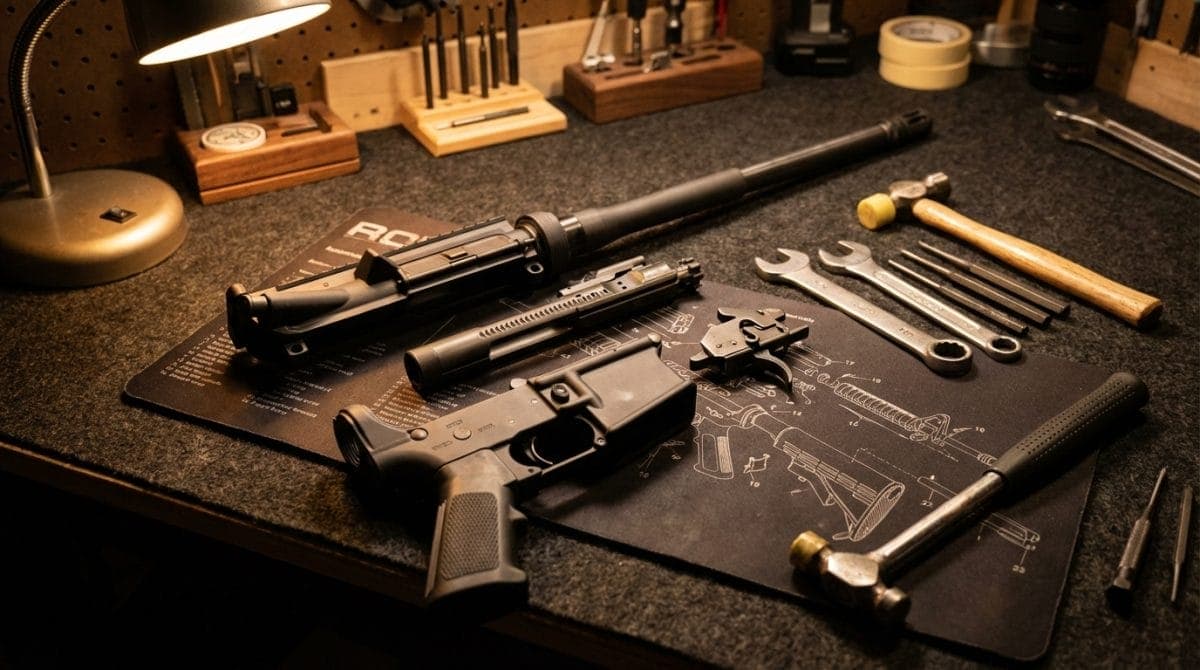
Essential Tools for AR-15 Lower Assembly
Proper tools make the difference between a smooth assembly and a frustrating experience. Here’s what you’ll need:
Required Tools
- AR-15 armorer’s wrench: For castle nut installation (30-40 ft-lbs torque)
- Roll pin punch set: 3/32″, 1/8″, and 5/32″ sizes minimum
- Hammer: Brass or nylon-tipped to prevent marring
- Roll pin starter punches: Prevent pin damage during installation
- Needle-nose pliers: For spring installation
- Torque wrench: 15-80 ft-lbs range covers all AR-15 applications
- Allen wrench set: For pistol grip screw (typically 3/16″)
- Masking tape: Protects receiver finish during assembly
- Bench block: Supports receiver during pin installation
Recommended Tools
- Pivot pin installation tool: Simplifies detent spring installation
- Bolt catch punch: Purpose-built for roll pin alignment
- Magazine well vise block: Secures lower during assembly
- Safety selector installation jig: Ensures proper detent alignment
Step-by-Step AR-15 Lower Receiver Assembly Instructions
Follow these steps carefully for successful AR-15 lower assembly. Work in a well-lit area with a padded surface to prevent parts loss and receiver damage.
Step 1: Install the Magazine Catch
Start with the magazine catch assembly as it’s one of the easier installations:
- Insert the magazine catch into the left side of the receiver, threading it through the magazine release slot
- From the right side, place the magazine catch spring over the threaded portion
- Thread the magazine catch button onto the catch, turning it clockwise
- Depress the magazine catch button fully and rotate the catch clockwise until the button sits flush or slightly recessed (typically 4-6 full rotations)
- Test function by pressing the button: the catch should spring back smoothly
Step 2: Install the Bolt Catch
The bolt catch installation requires careful pin alignment:
- Insert the bolt catch spring into the blind hole in the receiver (small end first)
- Place the bolt catch plunger on top of the spring
- Position the bolt catch over the plunger, aligning the roll pin holes
- Start the bolt catch roll pin using a 5/32″ starter punch
- Drive the pin flush with the receiver using a standard 5/32″ punch
- Apply 2-3 drops of blue threadlocker to the roll pin ends (optional but recommended)
Step 3: Install the Trigger Guard
Most builders find the trigger guard challenging due to the receiver ear’s fragility:
- Apply masking tape around both trigger guard pin holes
- Insert the trigger guard, aligning the holes (detent goes in the front hole)
- Support the rear ear with a bench block or specialized tool
- Start the trigger guard roll pin from the left side using a 1/8″ starter punch
- Drive the pin until it sits flush on both sides
- Remove masking tape and inspect for cracks
Step 4: Install the Pivot Pin
The front pivot pin installation benefits from a specialized tool but can be completed with basic tools:
- Insert the pivot pin detent into the front hole, pointed end up
- Compress the pivot pin detent spring and insert it above the detent
- Use a 1/4″ clevis pin or specialized tool to compress the spring while sliding in the pivot pin
- The pin should click into place with spring tension holding it
- Test retention by attempting to push the pin out without pressing the head
Step 5: Install the Fire Control Group
The trigger assembly represents the heart of your AR-15 lower build:
- Insert the trigger into the receiver, aligning the pin holes
- Install the trigger spring with legs resting on the trigger floor (legs point toward the rear)
- Insert the trigger pin from the left side, capturing the spring legs
- Place the disconnector into the trigger, orienting the hook forward
- Install the disconnector spring in the trigger’s center hole
- Position the hammer with the striking face forward
- Install the hammer spring with legs straddling the trigger pin (loop end toward hammer)
- Compress the hammer into the receiver and insert the hammer pin from the left side
- Verify smooth operation: the hammer should fall when the trigger is pulled
Step 6: Install the Safety Selector
Proper safety selector installation ensures positive engagement:
- Insert the safety detent into the grip-mounting hole, pointed end up
- Place the safety detent spring over the detent
- Rotate the safety selector to the “fire” position (pointing forward)
- Insert the selector from the left side, compressing the detent
- Rotate to “safe” position once fully seated
- The selector should click positively between positions
Step 7: Install the Pistol Grip
The pistol grip captures the safety detent spring:
- Ensure the safety detent spring remains in position
- Place the lock washer on the grip screw
- Insert the grip screw through the grip into the receiver
- Tighten to 35-40 inch-pounds (approximately 3 ft-lbs)
- Test safety selector function after installation
Step 8: Install the Takedown Pin
The rear takedown pin completes the basic lower assembly:
- Insert the takedown pin detent into the rear hole
- Place the takedown pin detent spring into the buffer tube threading
- Install the end plate, capturing the spring
- Thread the castle nut onto the receiver (do not tighten yet)
Step 9: Install the Buffer Tube Assembly
Proper buffer tube alignment affects stock function:
- Thread the buffer tube into the receiver 6-7 full turns minimum
- Align the tube so the stock mounting holes are perpendicular to the bore axis
- Slide the castle nut forward and hand-tighten
- Torque the castle nut to 30-40 ft-lbs using an armorer’s wrench
- Stake the castle nut in at least two places (military requirement, optional for civilian use)
- Insert the takedown pin, verifying spring tension
Step 10: Install the Buffer and Spring
Complete the buffer system:
- Insert the buffer spring into the tube (either end orientation works)
- Insert the buffer, ensuring it moves freely
- Install your chosen stock according to manufacturer instructions
Common Mistakes to Avoid During AR-15 Lower Assembly
Learning from others’ mistakes saves time and prevents damage:
Installation Errors
- Hammer spring orientation: Installing backwards reduces strike energy by approximately 40%
- Trigger spring placement: Legs must rest on the floor, not against the pins
- Over-torquing castle nut: Exceeding 40 ft-lbs can crack the receiver threads
- Forcing roll pins: Misaligned pins will bend; always verify alignment first
- Losing detent springs: Work over a container to catch launched parts
Function Check Failures
- Safety selector binding: Typically indicates incorrect detent orientation
- Trigger reset issues: Usually disconnector spring installed upside-down
- Hammer follow: Indicates improper disconnector engagement
- Magazine catch depth: Too shallow prevents magazine locking; too deep causes feeding issues
Testing Your Completed AR-15 Lower Assembly
Perform these function checks before attaching an upper receiver:
- Safety selector test: Should rotate 90 degrees with positive clicks
- Trigger pull test: With safety on “safe,” trigger should not move
- Hammer fall test: Pull trigger on “fire,” hammer should fall cleanly
- Reset test: Hold trigger back, manually reset hammer, release trigger slowly to feel reset
- Magazine insertion test: Empty magazine should lock positively and drop free when released
- Takedown pin test: Both pins should push out with firm pressure only
Troubleshooting Common AR-15 Lower Assembly Issues
Most assembly problems have straightforward solutions:
| Problem | Likely Cause | Solution |
|---|---|---|
| Safety won’t rotate | Detent installed backwards | Remove grip, reinstall detent pointed-end up |
| Trigger won’t reset | Disconnector spring upside-down | Remove hammer pin, flip spring orientation |
| Pins walk out | Missing or damaged detents | Replace det
Disclaimer: AR15 Outfitters does not sell firearms. This site is an information and affiliate resource only. All purchases are completed through licensed retailers. Always comply with all federal, state, and local laws when building or purchasing firearms and firearm components. |