AR-15 Upper Receiver Assembly: Step by Step
By AR-15 Outfitters · April 9, 2026
AR15 Outfitters may earn a commission on purchases made through links in this guide. This does not affect pricing or our recommendations.
Introduction to AR-15 Upper Receiver Assembly
Building your own AR-15 upper receiver assembly is one of the most rewarding aspects of the AR-15 platform. This comprehensive guide walks you through each step of the process, from gathering parts to final function checks. Whether you’re building your first AR-15 or your tenth, proper assembly technique ensures reliability, accuracy, and safety.
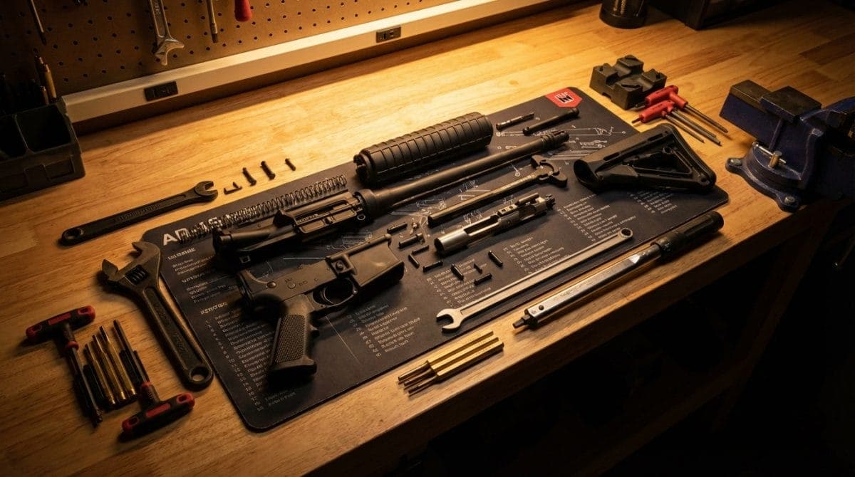
The upper receiver assembly houses the bolt carrier group, barrel, and gas system: the heart of your rifle’s operation. Unlike the lower receiver, which requires an FFL transfer, you can order all upper receiver parts directly to your door and complete the entire build at home with basic tools.
Complete Parts List for AR-15 Upper Assembly
Before starting your AR-15 upper receiver assembly step by step, verify you have all necessary components. Here’s what you’ll need:
- Upper Receiver – Forged or billet, stripped (Configure on AR15 Outfitters)
- Barrel – Length and profile of your choice
- Barrel Nut – Standard or proprietary depending on handguard
- Gas Block – Low-profile or front sight base (FSB)
- Gas Tube – Pistol, carbine, mid-length, or rifle length
- Handguard – Free-float or drop-in style
- Muzzle Device – Flash hider, brake, or compensator
- Forward Assist Assembly – Complete kit with spring and roll pin
- Ejection Port Cover Assembly – Door, spring, C-clip, and rod
- Bolt Carrier Group (BCG) – Complete assembly
- Charging Handle – Standard or ambidextrous
Small Parts Checklist
These small parts are often overlooked but essential for proper assembly:
- Gas tube roll pin (typically 5/64″ x 5/16″)
- Forward assist roll pin (typically 1/4″ x 5/8″)
- Ejection port cover spring
- Crush washer for muzzle device (if not included)
- Handguard mounting hardware (varies by manufacturer)
Required Tools for Upper Receiver Assembly
Having the right tools makes assembly significantly easier and prevents damage to parts:
Essential Tools
- Upper Receiver Vise Block – Clamshell or rod style
- Bench Vise – Minimum 4″ jaws recommended
- Torque Wrench – 1/2″ drive, capable of 80 ft-lbs minimum
- Barrel Nut Wrench – Specific to your barrel nut style
- Punch Set – Including 5/64″, 3/32″, and 1/8″ roll pin punches
- Hammer – Brass or nylon face preferred
- Armorer’s Wrench – Multi-tool for muzzle devices and castle nuts
Recommended Additional Tools
- Barrel Vise Jaws – For installing muzzle devices
- Roll Pin Starter Punches – Prevents mushrooming pins
- Bench Block – Provides support during pin installation
- Aeroshell 33MS or similar grease – For barrel nut threads
- Blue Loctite 242 – For gas block set screws
- Action Rod – Alternative to vise blocks for some operations
Step-by-Step AR-15 Upper Assembly Instructions
Step 1: Install the Forward Assist
Begin your AR-15 upper receiver assembly with the forward assist. This component allows manual bolt closure if needed.
- Insert the forward assist spring into the upper receiver cavity, large end first
- Compress the spring while sliding the forward assist pawl into position
- Align the roll pin holes through the receiver and forward assist
- Drive the roll pin flush using a 1/4″ punch (no specific torque required)
- Test function by pressing the forward assist button; it should spring back smoothly
Common mistake: Installing the spring backwards results in no spring tension. The larger diameter end goes into the receiver first.
Step 2: Install the Ejection Port Cover
The ejection port cover prevents debris from entering the action when closed.
- Insert the short leg of the C-clip into the forward pivot point
- Place the ejection port cover spring on the rod with the long leg pointing down
- Insert the rod through the rear pivot point, through the spring and cover
- Compress the assembly and snap the C-clip into the forward groove
- Hook the spring’s long leg under the cover and short leg into the receiver detent
Pro tip: The spring tension should close the door firmly but not slam it shut. Adjust the spring legs if needed.
Step 3: Barrel Installation
Proper barrel installation is critical for accuracy and safety. This step requires precision and the correct torque specifications.
- Secure the upper receiver in your vise block
- Apply a thin layer of grease (Aeroshell 33MS or equivalent) to the receiver threads
- Insert the barrel extension into the upper receiver, aligning the pin with the notch
- Hand-thread the barrel nut until it contacts the receiver face
- Torque to 30 ft-lbs initially
- Loosen completely, then retorque to 30 ft-lbs
- Continue tightening until the next gas tube hole aligns (typically 30-80 ft-lbs)
Critical specification: Maximum torque is 80 ft-lbs. If you cannot achieve gas tube alignment within this range, try adding or removing shims.
Step 4: Gas Block and Tube Installation
The gas system is essential for semi-automatic operation. Measure carefully for proper placement.
Gas Block Positioning
| Gas System Length | Port Distance from Receiver Face |
|---|---|
| Pistol | 4.0″ to 4.5″ |
| Carbine | 7.0″ to 7.5″ |
| Mid-length | 9.0″ to 9.5″ |
| Rifle | 12.0″ to 12.5″ |
- Slide the gas block over the barrel to the measured position
- Align the gas port in the block with the barrel’s gas port
- For set screw blocks: Apply blue Loctite 242 and tighten to 30 in-lbs
- For pinned blocks: Drill using the block as a guide, then drive the taper pin
- Insert the gas tube through the block, aligning the pin hole
- Drive the gas tube roll pin flush using a 5/64″ punch
Verification: The gas tube should extend into the receiver approximately 3.5″ to 4″ from the barrel nut face.
Step 5: Handguard Installation
Installation varies significantly by handguard type. Free-float rails typically offer better accuracy potential.
Free-Float Handguard
- Install the proprietary barrel nut if required (follow manufacturer’s torque spec)
- Time the barrel nut if it has anti-rotation tabs
- Slide the handguard over the barrel nut
- Tighten mounting screws to manufacturer’s specification (typically 35-55 in-lbs)
- Verify the handguard doesn’t contact the gas block
Drop-In Handguard
- Install the delta ring assembly and handguard cap during barrel installation
- Compress the delta ring using the armorer’s wrench
- Insert the rear of both handguard halves
- Pivot forward and release the delta ring
Step 6: Muzzle Device Installation
Proper timing and torque ensure your muzzle device functions correctly and remains secure.
- If using barrel vise jaws, secure the barrel near the muzzle
- Check muzzle threads for damage or debris
- Install crush washer with the tapered side facing the muzzle device
- Thread the muzzle device hand-tight
- Torque to 15-20 ft-lbs while timing ports/slots as needed
- Verify proper alignment if using a suppressor mount
Note: Shims may be required instead of a crush washer for devices requiring precise timing.
Step 7: Final Assembly and Function Check
- Insert the charging handle into the upper receiver channel
- Pull the charging handle back approximately 3 inches
- Insert the bolt carrier group with the bolt in the forward position
- Release the charging handle to seat fully forward
- Perform function check: cycle the action several times smoothly
Common Mistakes to Avoid
Learning from others’ experiences helps ensure a successful build:
Over-torquing the Barrel Nut
Exceeding 80 ft-lbs can damage receiver threads or cause stress fractures. If you can’t achieve gas tube alignment within spec, use shims rather than additional torque.
Incorrect Gas Block Alignment
Misaligned gas ports cause short-stroking or complete failure to cycle. Always verify alignment visually through the gas tube hole before final tightening.
Damaged Roll Pins
Using the wrong size punch mushrooms pin ends. Start pins with a roll pin starter punch, then drive home with the correct size punch.
Loose Handguard
Insufficient torque on mounting hardware causes point of impact shifts. Always use a torque wrench and thread locker where specified by the manufacturer.
Cross-threaded Muzzle Device
Starting threads at an angle permanently damages both parts. Always start threading by hand before using tools.
Testing Your Completed Upper
Before heading to the range, perform these checks:
- Headspace: While modern AR-15 parts typically have correct headspace, gauging is recommended for maximum safety
- Gas tube alignment: Insert the BCG slowly to verify the gas key enters the tube smoothly
- Barrel nut torque: Re-check with torque wrench after 50-100 rounds
- Handguard clearance: Verify no contact with gas block under pressure
Build This on AR15 Outfitters
Ready to build your own AR-15 upper receiver? The AR15 Outfitters Builder makes parts selection simple with real-time compatibility checking and price comparison across multiple retailers. Our builder ensures all your components work together while finding the best deals available.
Start by selecting your upper receiver, then the builder guides you through each component selection with compatibility filtering. See real-time pricing from trusted retailers, read community reviews, and save your build configuration for future reference. Whether you’re assembling a precision rifle upper or a lightweight build, AR15 Outfitters helps you make informed decisions and avoid costly compatibility mistakes.
Visit ar15outfitters.com/builder to start configuring your perfect AR-15 upper receiver assembly today. With thousands of parts combinations and up-to-date pricing, you’ll find exactly what you need for your build.
Disclaimer: AR15 Outfitters does not sell firearms. This site is an information and affiliate resource only. All purchases are completed through licensed retailers. Always comply with all federal, state, and local laws when building or purchasing firearms and firearm components.