How to Build an AR-15 Lower Receiver: Step-by-Step Guide
By AR-15 Outfitters · April 9, 2026
AR15 Outfitters may earn a commission on purchases made through links in this guide. This does not affect pricing or our recommendations.
Building your first AR-15 lower receiver marks an important milestone in your journey as an AR-15 builder. This comprehensive guide walks you through every step of assembling a stripped lower receiver into a fully functional foundation for your rifle. Whether you’re a first-time builder or looking to refine your technique, understanding the proper assembly process ensures a reliable and safe firearm.
Understanding the AR-15 Lower Receiver
The lower receiver serves as the serialized firearm component and houses the fire control group, magazine well, and buffer tube attachment point. When you build an AR-15, starting with the lower provides immediate satisfaction: you’ll have a functioning firearm receiver that accepts any compatible upper receiver assembly.
A stripped lower typically weighs between 8.5 and 10 ounces for forged aluminum models, with billet receivers generally weighing 1 to 3 ounces more due to additional material. The receiver pocket dimensions are standardized: the fire control cavity measures approximately 1.249 inches wide with specific pin hole locations at 0.250 inches diameter for the hammer and trigger pins.
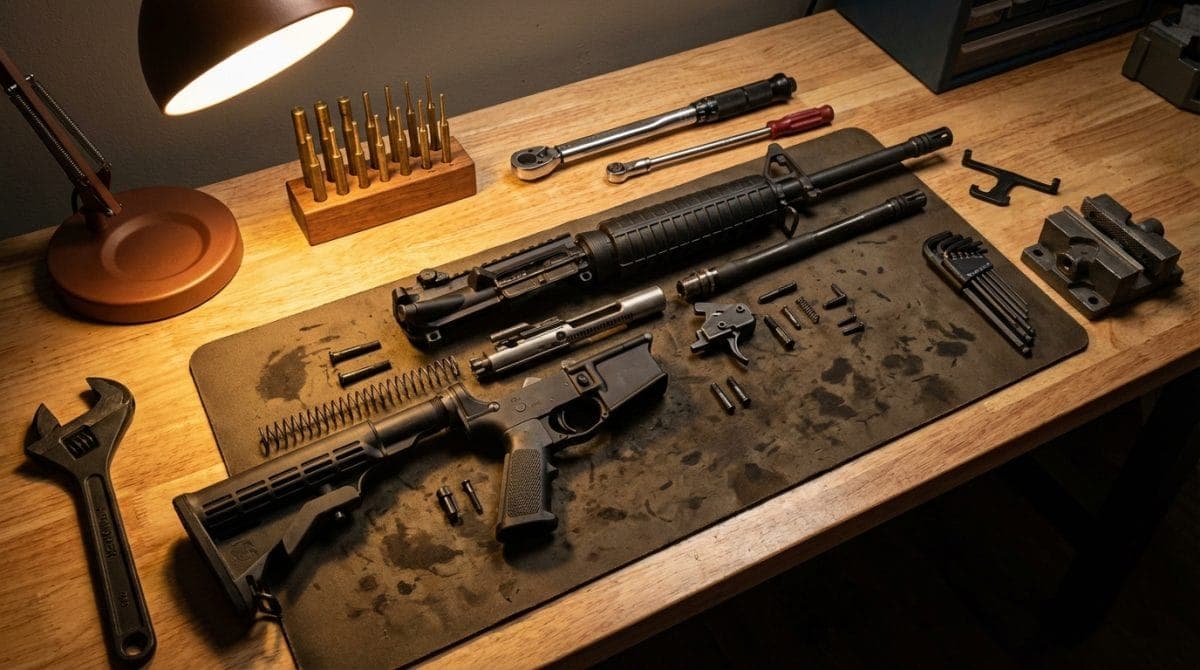
Required Tools for Lower Assembly
Proper tools make the difference between a smooth build experience and potential damage to your parts. Here’s what you’ll need:
- Punch set: Steel punches in 1/16″, 3/32″, 1/8″, and 5/32″ sizes
- Hammer: Brass or nylon-faced hammer to prevent marring
- Needle-nose pliers: For spring installation
- Castle nut wrench: Specifically designed for buffer tube installation
- Torque wrench: Essential for proper castle nut torque (40 ft-lbs)
- Vise block: Lower receiver vise block for secure work positioning
- Masking tape: Protects the receiver finish during assembly
- Safety glasses: Springs can launch unexpectedly
Optional but Helpful Tools
- Pivot pin installation tool: Simplifies detent spring installation
- Bolt catch punch: Purpose-built tool prevents slipping
- Lower receiver action block: More secure than standard vise blocks
Complete Parts List
A standard AR-15 lower assembly requires these components. Most builders purchase a complete lower parts kit (LPK) that includes everything except the pistol grip, trigger group, and buffer tube assembly:
Lower Parts Kit Components
- Magazine catch: Body, spring, and button
- Bolt catch: Catch, plunger, spring, and roll pin
- Pivot pin: Pin, detent, and spring
- Takedown pin: Pin, detent, and spring
- Safety selector: Selector lever, detent, and spring
- Trigger guard: Guard body and roll pin
- Magazine release button
Fire Control Group
- Trigger: Trigger body, spring, and pin
- Hammer: Hammer body, spring, and pin
- Disconnector: Disconnector and spring
Buffer Tube Assembly
- Buffer tube: Carbine (7 inches) or rifle (9.5 inches) length
- Buffer: Weight varies from 2.5 oz (carbine) to 5.4 oz (rifle)
- Buffer spring: Carbine or rifle length to match tube
- Castle nut: Secures buffer tube to receiver
- End plate: Provides castle nut bearing surface
Grip and Stock
- Pistol grip: A2 or aftermarket design
- Grip screw: Typically 1/4-28 thread
- Lock washer: Prevents grip screw loosening
- Stock: Fixed or collapsible design
Step-by-Step Assembly Process
Follow these steps in order for the smoothest assembly experience. Take your time: rushing leads to lost detent springs and scratched receivers.
Step 1: Install the Magazine Catch
Start with the magazine catch assembly. This three-part system requires careful coordination:
- Insert the magazine catch through the left side of the receiver
- Thread the magazine catch spring onto the catch from the right side
- Depress the spring and thread on the magazine release button
- Push the magazine catch fully left and rotate the button clockwise
- Continue rotating until the button sits flush with the receiver exterior
- The catch should have approximately 0.020 to 0.040 inches of side-to-side play
Step 2: Install the Bolt Catch
The bolt catch represents one of the more challenging installations due to spring tension:
- Insert the bolt catch spring into the receiver pocket (large end first)
- Place the bolt catch plunger on top of the spring
- Position the bolt catch over the plunger while compressing the spring
- Align the bolt catch holes with the receiver pin holes
- Drive the roll pin through using a 3/32″ punch
- Start the pin with light taps, ensuring centered alignment
- The pin should sit flush on both sides when complete
Step 3: Install the Pivot Pin
Detent springs love to launch across the room. Use this technique to maintain control:
- Apply masking tape over the pivot pin detent hole
- Insert the detent spring (small end first) into the hole
- Place the detent on top of the spring
- Use a 1/8″ punch through the tape to compress the detent
- Slide the pivot pin in from the side while maintaining compression
- The pin should capture the detent, allowing removal of the punch
Step 4: Install the Trigger Guard
Many builders skip this step with integrated trigger guard receivers, but standard receivers require installation:
- Insert the trigger guard front tab into the receiver slot
- Rotate the guard into position
- Support the receiver ears with a solid backing
- Drive the roll pin through the rear attachment point
- Check for smooth trigger guard operation
Step 5: Install the Fire Control Group
Proper trigger installation directly impacts your rifle’s performance and safety:
- Insert the trigger into the receiver with the spring legs forward
- Install the disconnector into the trigger with its spring
- Align the trigger pin holes and insert the trigger pin from left to right
- Position the hammer with spring legs resting on the trigger pin
- Compress the hammer spring and align the hammer pin holes
- Insert the hammer pin from left to right
- Function check: the hammer should fall when the trigger is pulled
- With the hammer down, the disconnector should catch when cycled back
Step 6: Install the Safety Selector
The safety selector requires the hammer to be cocked for proper installation:
- Cock the hammer to the rear position
- Insert the safety detent into the grip screw hole (pointed end up)
- Place the safety spring on top of the detent
- Insert the safety selector from the left side (on “SAFE” marking)
- Rotate 90 degrees to “FIRE” and back to verify function
- The selector should have positive detent engagement at both positions
Step 7: Install the Pistol Grip
The grip captures the safety selector spring and detent:
- Ensure the safety spring sits in the grip’s spring pocket
- Carefully align the grip with the receiver
- Insert the grip screw with lock washer
- Tighten to approximately 25 inch-pounds
- Verify the safety selector still functions properly
Step 8: Install the Buffer Tube Assembly
Proper buffer tube installation prevents catastrophic failure during firing:
- Place the end plate against the receiver with the tab facing down
- Thread the castle nut onto the receiver (teeth facing forward)
- Insert the takedown pin detent and spring into the rear hole
- Compress the spring with the buffer tube as you thread it on
- Thread the buffer tube until it covers the detent spring
- Align the buffer tube so the stock attachment point faces directly up
- Slide the castle nut and end plate against the receiver
- Torque the castle nut to 40 ft-lbs using a castle nut wrench
- Stake the castle nut in at least two positions using a center punch
Step 9: Install the Takedown Pin
With the buffer tube capturing the detent spring, installation becomes straightforward:
- Insert the detent into the rear takedown pin hole
- Slide the takedown pin in from the side
- The pin should have smooth operation with positive detent stops
Step 10: Final Assembly
Complete your lower with these final components:
- Insert the buffer and buffer spring into the buffer tube
- The buffer should compress approximately 3.25 inches on a carbine system
- Install your chosen stock according to manufacturer specifications
- Perform a complete function check of all controls
Function Checks and Safety Verification
After assembly, perform these important safety checks:
Trigger Function Test
- Hammer Release: Pull trigger, hammer should fall smoothly
- Disconnector Function: Hold trigger, cycle hammer, release trigger slowly
- Reset Test: You should hear/feel a click as the disconnector releases
- Safety Test: With hammer cocked and safety on “SAFE,” trigger should not move
Measurement Verification
- Trigger Pull Weight: Typically 5.5 to 8.5 pounds for mil-spec triggers
- Safety Selector Travel: Exactly 90 degrees between positions
- Magazine Insertion Depth: Magazine should lock positively without excessive force
- Buffer Tube Alignment: Measure 0 degrees deviation from vertical
Tips for First-Time Builders
Learn from common mistakes to ensure a successful first build:
Organization is Key
Use a magnetic parts tray or divided container to organize small parts. Label each section if working with multiple builds. A white towel provides contrast for finding dropped detents.
Take Your Time
Most assembly errors occur from rushing. Budget 2 to 3 hours for your first lower assembly. Professional builders typically complete the process in 30 to 45 minutes with experience.
Protect Your Investment
Apply painter’s tape to areas where tools will contact the receiver. Even experienced builders occasionally slip with punches. The tape prevents costly refinishing.
Spring Control Techniques
Work inside a large clear plastic bag when installing detent springs. This contains launched springs while maintaining visibility. Alternatively, work over a clean bedsheet to catch flying parts.
Proper Support
Never hammer on an unsupported receiver. Use proper vise blocks or support the specific area you’re working on. Cracked receiver ears from improper trigger guard installation remain a common mistake.
Common Assembly Issues and Solutions
Stuck Roll Pins
If a roll pin won’t start, verify you’re using the correct size. Bolt catch pins measure 5/32″ while trigger guard pins are typically 1/8″. A drop of oil helps pins slide easier.
Safety Selector Won’t Rotate
This typically indicates the hammer isn’t fully cocked or the detent spring applies too much pressure. Verify the safety detent moves freely in its channel.
Trigger Pin Walk
Pins that work loose during operation suggest improper spring tension or worn parts. Anti-walk pins provide a solution for problematic triggers.
Magazine Won’t Drop Free
Check magazine catch adjustment. The button should sit flush with the receiver exterior. Additional rotation deepens magazine engagement.
Recommended Parts
Selecting quality components ensures reliable function and compatibility. The AR15 Outfitters Builder simplifies parts selection by showing only compatible options for your build.
Lower Receivers
Start with a quality forged or billet lower receiver from the AR15 Outfitters Builder. Forged receivers typically cost $50 to $150, while billet options range from $150 to $400. Consider features like integrated trigger guards and enhanced magazine wells based on your intended use.
Lower Parts Kits
Complete lower parts kits available through the AR15 Outfitters Builder range from basic mil-spec options at $40 to enhanced kits with upgraded components at $150+. Match your LPK quality to your overall build goals.
Triggers
The AR15 Outfitters Builder offers triggers from basic mil-spec to competition-grade options. Single-stage triggers typically break at 4.5 to 6 pounds, while two-stage triggers offer more control with total weights from 2.5 to 4.5 pounds.
Disclaimer: AR15 Outfitters does not sell firearms. This site is an information and affiliate resource only. All purchases are completed through licensed retailers. Always comply with all federal, state, and local laws when building or purchasing firearms and firearm components.